August 2011, Vol. 238 No. 8
Features
Advances In ILI Allow Assessing Unpiggable Pipelines
Advances in inline inspection (ILI) tools and other inspection technology today allow for detailed assessment of unpiggable or difficult-to-pig pipelines. In pipe systems considered unpiggable or difficult-to-pig, hydrotesting has been the primary fitness-for-service (FFS) assessment methodology. While regulatory compliance may be achieved by hydrotesting some lines, such testing does not provide a complete picture of the condition of a pipeline.
Inline inspection (ILI) now allows operators to gather a large amount of inspection data about systems on which they previously were only able to obtain very little or incomplete information. In addition to collecting information, the quality and resolution of the available data is also increasing. High-resolution inspections can accurately size the length and depth of an anomaly, but with the appropriate inline inspection tool and supporting software, it is now possible to go beyond traditional assessment methodologies and to run advanced Level 2 (Effective Area) assessments on areas of metal loss or to build a finite element model of individual dents in order to assess fitness-for-service (FFS). The advantages of inspecting a difficult-to-pig pipeline with high resolution inline inspection technology are demonstrated in the following case study.
Operational Logistics
Quest Integrity Group was contracted to inspect 3.5 miles of 12-inch pipe running from a tank farm to a refinery. The pipeline is constructed of ERW and seamless pipe with nominal wall thicknesses varying from 0.219-inch to 0.500-inch. The pipeline supplies the crude feed from the offsite tank farm to the refinery. The ability to mobilize and provide high-quality results quickly was vital to the execution of this project due to limits imposed by a scheduled refinery shutdown.
Typically, this operator utilizes magnetic flux leakage (MFL) ILI technology for inspecting pipelines and ensuring regulatory compliance. However, an as-built survey indicated a 90-degree bend with a possible bend radius of 1D or a mitered bend. Additionally, a minimum bore of 10.25-inch was discovered with a gauge plate. The 16% reduction could not be negotiated by the MFL tool. Within a week of being contacted, Quest Integrity mobilized a crew and inspected the pipeline with its InVista™ inline inspection technology. These tools are compression-wave ultrasonic ILI tools that are designed to navigate unpiggable and difficult-to-pig pipelines such as those with bore restrictions, limited or no launcher facilities, low flow conditions, unknown pipeline conditions due to limited records, significant wall thickness variations, or single entry/exit points. Not only can the tool negotiate difficult-to-pig pipelines, this unique technology records accurate and high resolution wall thickness measurements in combination with internal radius measurements. Although this ILI tool utilizes ultrasonic technology, successful inspections of gas lines have been completed by batching the pig in a liquid product for those operators that prefer inline inspection over hydrotesting and require the navigational capabilities of the InVista tool.
For this inspection, the 12-inch inspection tool was introduced into the launcher at the tank farm and was received at the refinery site. Upon retrieval of the tool, the ultrasonic measurement data was downloaded and prepared for preliminary analysis. Diagnostic review and visual inspection established that the data quality was acceptable for further analysis and assessment.
Data Analysis And Assessment
Today’s high-resolution inline inspection technology provides improved data on pipeline condition, enabling advanced assessment capabilities. With the use of advanced engineering methodologies, pipeline operators can not only assess individual anomalies but determine overall pipeline FFS efficiently and confidently.
As part of Quest Integrity’s standard reporting service, an API 579-1/ASME FFS-1 2007 Level 2 FFS assessment was performed on the 12-inch line inspection from the tank farm to the refinery. The pipeline maximum operating pressure (MOP) was provided as 720 psig. The pipeline inspection data was analyzed for wall thinning and anomalies such as corrosion, denting and ovality. Data from the analysis was assessed using the LifeQuest™ pipeline software to determine the remaining strength factor (RSF) and reduced maximum allowable operating pressure (MAOPr) for every joint of pipe throughout the pipeline.
This assessment was based on the longitudinal extent of thinning found in the pipeline and in accordance with a Level 2 Assessment found in Part 5 of the API 579 standard. The minimum MAOPr calculated according to the Part 5 Level 2 assessment methodology in API 579 was 961 psig. Based upon the inspection data, the pipeline satisfies API 579 Part 5 Level 2 FFS criteria for any MOP equal to or below the highest listed design MOP of 720 psig. Twenty-eight metal loss features and 16 dents were individually identified. No features met 49 CFR 195.452 immediate condition criteria for metal loss exceeding 80% or dents exceeding 6% OD.
During analysis of the inline inspection data, 179 field bends were individually identified. Figure 1 demonstrates how internal radius data from a high resolution in-line inspection tool can provide detailed information about field bend geometry, supporting initial screening and advanced fitness-for-service if required.

Figure 1: Internal Radius Data at Field Bend.
An initial screening process can include measurements from the inline inspection data such as maximum depth, severity ratio (i.e. height/length) and bending strain calculated from the bend profile extracted from the ILI data. These results can be combined with additional information such as pipeline operating history, pipeline materials and the operator’s anomaly response program in order to determine if field bends require excavation and/or further assessment such as API 579 Level 3 FFS.
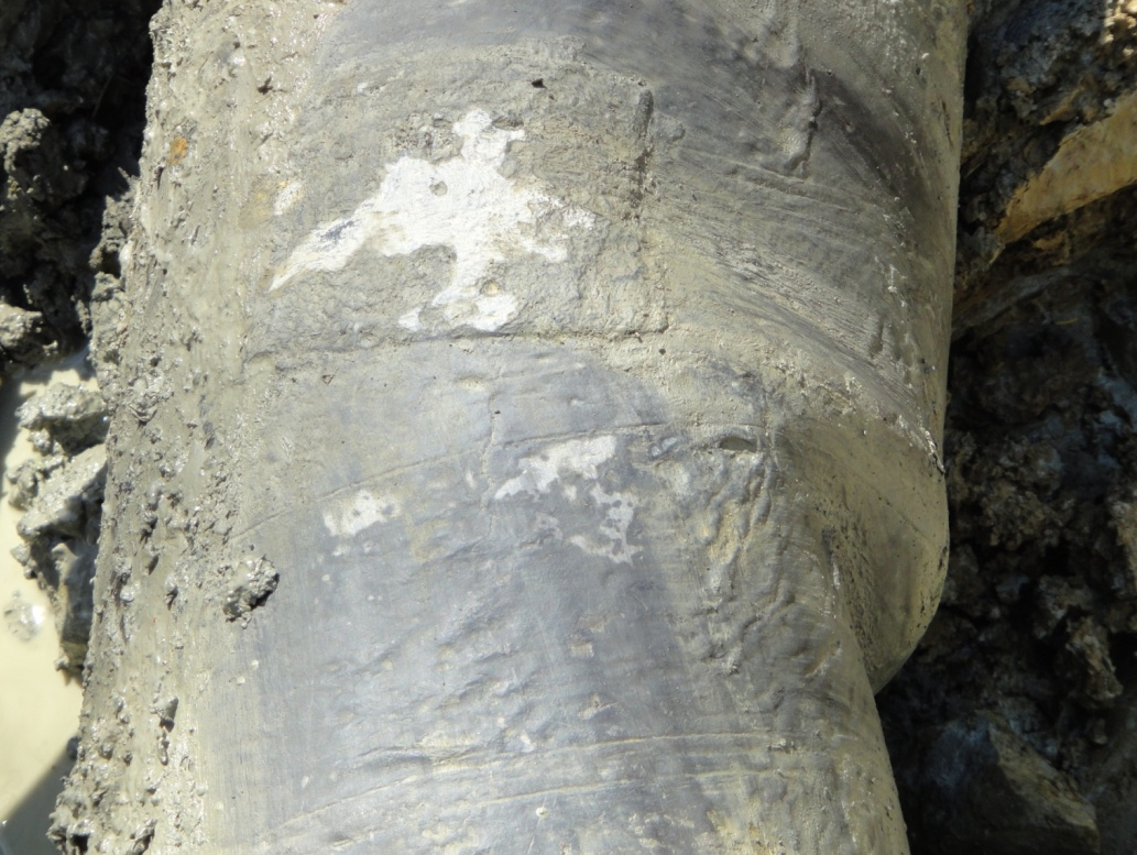
Of the 179 field bends identified, three were identified as “possible wrinkles.” Initial excavations confirmed wrinkling in excess of 6% OD at one of the field bends as seen in Figure 2.
Based on the operator’s anomaly response program, mitigation included a 20% reduction in normal operating pressure and permanent repair within 365 days of discovery. In order to determine pipeline fitness-for-service at the location of the wrinkle and the ability to continue operating at current pressures until the scheduled re-inspection, a Level 3 FFS assessment was requested by the operator.
Level 3 FFS
An FFS assessment is a quantitative engineering evaluation that is performed to demonstrate the structural integrity of an in-service component that may contain a flaw or damage. Level 3 FFS is a detailed evaluation that can include numerical analysis techniques such as finite element analysis (FEA) and requires engineering expertise in complex FFS assessments.
Quest Integrity performed the Level 3 FFS assessment per API 579-1/ASME FFS-1 2007. FEA was used to determine stresses in the wrinkled portion of the 12-inch pipeline. Maximum principal through-wall stresses were identified and used for fatigue life estimation, critical crack sizing and crack growth analysis.
Implementation of Level 3 FFS requires information about pipe geometry, operating conditions and pipe materials. For this case study, the wrinkle geometry and pipe geometry in the vicinity of the wrinkle were derived from the ILI data, scaled photographs taken in the field, and x-ray scans that provided detailed topography of the inside diameter, outside diameter, and wall thickness. Internal operating pressures were supplied by the operator.
The minimum pressure experienced by the pipeline is 65 psig and the maximum pressure experienced is 205 psig, resulting in a maximum pressure fluctuation of 140 psig per cycle. Based on information supplied by the operator, two cycles are expected per year. Operating temperatures range from 45-75 degrees F. Representative material properities were chosen based on the maximum operating temperature of 75 degrees F. This pipeline is constructed of API 5L Grade B carbon steel.
Since the exact elemental composition of the steel is not known, a typical yield strength of 35 ksi and an ultimate tensile strength of 60 ksi were conservatively assumed for the assessment. Mechanical properties were taken from industry literature and – in lieu of material testing – lower-bound fracture toughness was used, increasing the conservatism of the assessment. For ferritic and austenitic steels in non-aggressive environments, with yield strength less than 87 ksi, API 579 Annex F Section 5.3.2 provides estimated Paris law fatigue crack growth properties.
Specifically, these properties include a coefficient (C), an exponent (m), and threshold stress intensity (Kth). Stress intensity represents the driving force available to propagate a crack. Provided that the stress intensity of the crack remains below the threshold, it will not propagate due to cyclic loading (fatigue).
A three-dimensional FEA mesh was created to model the geometry and boundary conditions of the 12-inch pipe with a nominal wall thickness of 0.250 inch. The finite element model was run using the Abaqus finite element solver, a fully functional and validated commercial FEA software package. The Abaqus FEA software was used to conduct the linear elastic analysis of the pipeline bend. The stress state at the 205 psig obtained with the elastic analysis represents the maximum stress state in the pipeline.
Resulting Von Mises stresses in the wrinkled region of the pipeline, at 205 psig and a temperature of 75 degrees F, are relatively low, with a maximum stress of 24.2 ksi. Thus, there is no apparent pressure-induced yielding in the wrinkle because the maximum Von Mises stress resulting from the highest internal pressure is just below 70% of the yield stress. No plastic (non-recoverable) deformation is expected in the wrinkle due to pressure loading.
In Figure 3, overall stresses in the pipeline are low, with the highest elastic maximum principal stress being 27.7 ksi, located on the external surface of the wrinkle and oriented in the axial direction. Through-thickness maximum principal stresses at this location range from 27.7 ksi at the OD (0% through-thickness) to 0.038 ksi at the ID (100% through-thickness). Stresses rapidly decay away from the wrinkle. Maximum principal through-thickness stresses were used for fatigue life estimation, critical crack sizing and crack growth analysis.

Figure 3: Elastic Maximum Principal Stress (psi): 205 psi, 75 degrees F.
Crack initiation was assessed using the welded joint fatigue curves in Annex F of the API 579 Fitness-for-Service Standard. Estimated time for fatigue crack initiation is 73,000 years. Critical crack sizes were computed using Signal™ Fitness-for-Service software. Signal is a fully validated software package, produced by Quest Integrity, which implements Level 1 and Level 2 assessment methodologies found in API 579.
The crack propagation fatigue life was assessed using Part 9 of the API 579 Fitness-for-Service Standard, employing the Paris equation to establish crack growth. This analysis determines the time required for a small flaw, such as one initiated by fatigue, to propagate due to cyclic loading and cause a leak or sudden failure of the line. As seen in Figure 4, growing from a minimum detectable crack size reference to a critical flaw size requires approximately 111,000 cycles or 55,500 years.
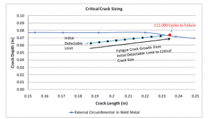
Figure 4: Fatigue Crack Growth.
FFS assessment and fatigue analysis at the location of the wrinkle supports continued use of the pipeline at the specified operating conditions and planned re-inspection interval. The analysis is based on InVista inspection data and information provided by the operator. Additional loading or failure mechanisms are not known or included in the assessment.
Advantages For Operator
Advances in inline inspection technology and engineering assessment techniques enable operators to make more prudent and cost effective decisions about pipeline integrity.
In this case study, the unique abilities of the high-resolution inline inspection tool enabled the operator to inspect a difficult-to-pig pipeline, allowing continued monitoring of the pipeline instead of relying on hydrotesting and a snap-shot view of integrity. The ability to mobilize quickly and complete a successful inspection on the first run met the critical time frame requirements of the operator. The combination of wall thickness and internal radius measurement capabilities provided detailed information about metal loss features, dents and field bends.
With high-resolution ILI data and supporting software it is possible to accurately and automatically implement Level 2 FFS. Furthermore, high-resolution ILI data can be used as a basis in advanced engineering assessments such as a Level 3 API 579 Fitness-for-Service approach, providing valuable FFS and fatigue life information that can be used when making critical pipeline operation and integrity management decisions.
Authors
Lisa Barkdull holds the position of senior consultant – Pipeline Specialist with Quest Integrity Group. She has over 18 years of experience in the pipeline service industry with a primary focus on analysis of inline inspection (ILI) data. She has worked in various ILI disciplines including data analysis, engineering, QA/QC and management. Contact information: info@questintegrity.com, www.questintegrity.com.
Ian Smith has worked in the pipeline industry for more than 15 years and is employed by Quest Integrity Group as senior consulting engineer, Pipelines. He has extensive experience in pipeline integrity programs, project management, pipeline engineering, risk management, incident investigation, loss control, hydraulic modeling, and pipeline operations.
Comments