February 2022, Vol. 249, No. 2
Features
Thermal-Mass Measurement Principle and Metering Selection
By Michele Monitaro, Industrial Market, and Konrad Domanski, Gas Metering Solutions, Sensirion
The European Green Deal is the strategic plan to make the European Union carbon neutral by 2050.[1] Decarbonizing the energy sector will be vital to achieving this goal, as this sector contributes significantly to Europe’s CO2 emissions.[2]
A promising strategy in this respect is gradually replacing natural gas with renewable gases, such as sustainably produced hydrogen or biogas. The use of hydrogen, in particular, is likely to be a favorable course of action, and preparations are already underway to transition the entire gas infrastructure to this plan (e.g., starting in 2025, all new gas boilers sold in the U.K. must be compatible with pure hydrogen).
Gas meters are an essential part of gas infrastructure, and they are indispensable in reliability and fair gas consumption billing.
In this article, we will examine the metrological behavior of thermal-mass gas meters operating with natural gas mixtures containing significant amounts of hydrogen and pure hydrogen. We will present measurement data, discuss measurement accuracy and operational safety, and explain why it will still be possible to maintain thermal-mass gas meters’ compact size regardless of the hydrogen content, which is the key advantage that hydrogen-ready solutions have over the other metering technologies.
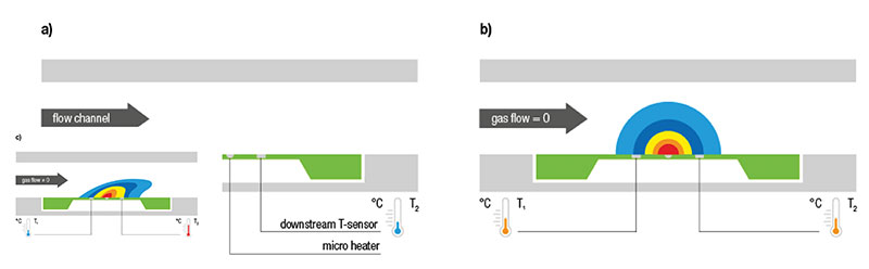
A calorimetric sensor element based on MEMS (micro-electromechanical system), as shown in Figure 1a, is the core element of any thermal-mass flow sensor, such as those used in gas meters.
The sensor element can be found on a silicon chip membrane and consists of a micro-heating element and temperature sensors that are integrated upstream and downstream. When an electric current flows through the micro-heating element, it generates a temperature profile on the membrane.
If no gas is flowing, the temperature is identical at both the upstream and the downstream temperature sensors (Figure 1b). If gas flows across the membrane, it generates a heat flow – in other words, it causes the temperature profile on the membrane to change – resulting in a temperature change between the upstream and downstream temperature sensors (Figure 1c).
The resulting difference in temperature between the two sensors creates a precisely measurable sensor signal that is a function of the flow velocity: the greater the difference in temperature, the greater the gas’s flow velocity over the sensor element.
The thermal-mass flow measurement principle is based on the physical effect of heat convection, so the sensor signal depends on both the gas’s flow velocity across the membrane and the measured gas mixture’s thermal properties.
So, a thermal flow sensor provides accurate measurement data if it either has been precalibrated for a particular gas mixture or if it has a routine that dynamically takes into account varying gas mixtures when measuring flow.
Gas meters can be used for a large number of potential gas mixtures, and their composition can vary over time. In practice, it is not feasible to perform individual pre-calibrations for all the possible natural gas mixtures, which is why Sensirion’s thermal-mass sensors for gas meters have a proprietary, dynamic natural gas and hydrogen recognition routine to ensure accurate flow measurements, even when gas compositions vary.
Test Setup
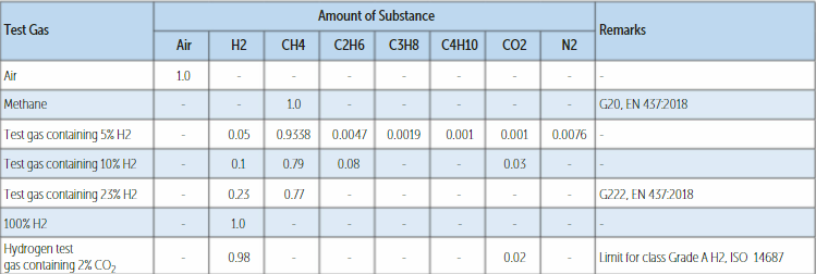
The measurement data presented here were recorded using thermal-mass flow sensors with a dynamic gas recognition routine. The routine is optimized for H, L and E gases that contain up to 23% hydrogen, according to EN 437:2018, as well as for pure and near-pure hydrogen. The flow sensors’ output signal is temperature- and pressure-compensated in standard cubic meter per hour (m3/h).
The flow sensors were tested in a generic gas meter prototype housing, with the flow sensor positioned at the gas meter housing outlet (Figure 2a). An external gas supplier mixed the tested gas mixtures (Table 1).[3] Sonic nozzles were used as flow references and the measurements were conducted at room temperature.[4] Figure 2b shows the measurement setup for the flow measurements.
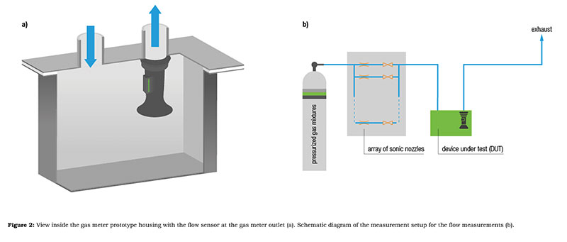
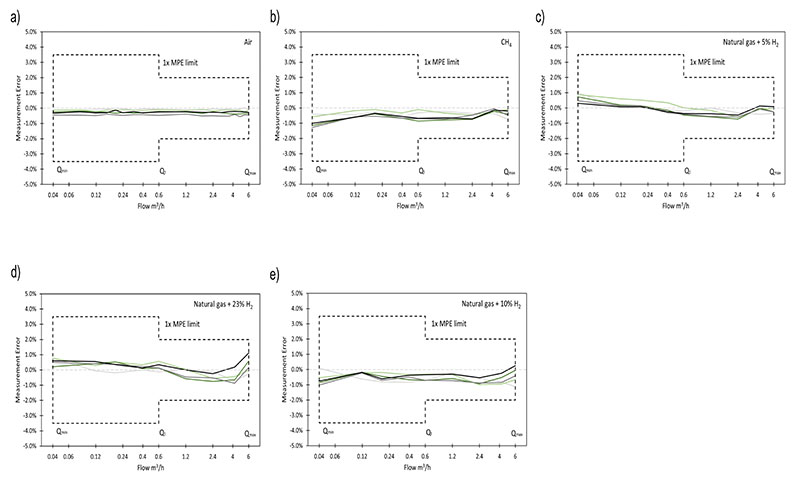
Figure 3 shows the relative measurement errors at the reference gas flow of up to 6 m3/h (G4 meter) for five flow sensors in air, methane and natural gas mixtures containing 5%, 10% and 23% hydrogen.
The error limits of ±3.5% and ±2% (in black) are the maximum permissible error limits according to the European Directive 2016/32/EC on measuring instruments (MID) and the recommendations made by the International Organization of Legal Metrology OIML R 137 regarding accuracy temperature-compensated gas meters of accuracy Class 1.5.
All the error curves of each of the five measured flow sensors are well within the maximum permissible error limits and comply with the permitted air-gas relationship of 3% and 1.5%, respectively, according to the European Standard for thermal-mass gas meters, EN 17526, as well as EN 14236 for ultrasonic domestic gas meters.
The test gas containing 23% hydrogen is the test gas G 222 according to EN 437. G 222 is described as the “limit test gas” – a gas mixture with the maximum hydrogen content used for testing gas appliances for second-family natural gas mixtures, according to EN 437.
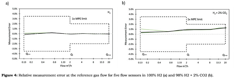
Since hydrogen has a lower calorific value (lower than that of natural gas by a factor of three), significantly higher hydrogen flow rates are required to maintain the same energy flow through the meter. Figure 4 shows the relative measurement errors at the reference gas flow of up to 20 m3/h for five flow sensors in 100% H2 and 98% H2 + 2% CO2. Two percent of impurities is the maximum allowed for Class A hydrogen as defined by ISO 14687. Again, the error limits for Class 1.5 meters of ±3.5% and ±2.0% are indicated in black (for a meter with Qmax of 20 m3/h).
The meters perform very well when working with both pure hydrogen and hydrogen with 2% of CO2 contamination. The size of the sensor (and, consequently, the meter) can stay the same whether it operates with a 6-m3/h flow of natural gas or 20 m3/h of hydrogen.
Operational Safety
Sensirion’s thermal-mass flow sensors do not have any safety-related limitations when operated with natural gas or hydrogen. Both the maximum temperature and the maximum thermal energy stored on the micro-sensor element are significantly below hydrogen/air mixtures’ ignition temperature or ignition energy, even if the flow sensor’s voltage regulator malfunctions.
This is why Sensirion’s thermal-mass flow measurement technology has been successfully used for years in challenging gas analysis applications with pure hydrogen.
When substituting natural gas with hydrogen, it is important to bear in mind that hydrogen’s calorific value by volume is about three times lower than that of typical natural gas mixtures.[5] In practice, this means that, if a gas appliance is operated with pure hydrogen instead of natural gas, a gas volume approximately three times greater must be supplied to achieve comparable heating power.
In this case, gas meters originally designed for operation with natural gas need to be capable of measuring an increased gas volume due to the admixture of hydrogen. Consequently, it may be necessary to choose purely volumetric natural gas meters in a larger size that also have an extended dynamic range (if they have to be compatible with both natural gas and pure hydrogen).
Larger meter designs can be more costly and require more installation space. If larger gas volumes flow through a meter than what it was originally designed for during operation with hydrogen-free natural gas, this can increase the wear on the meter mechanics, thus shortening the service life.
Similarly, ultrasonic gas meters face a challenge due to hydrogen having an increased speed of sound compared to that in natural gas (approximately by a factor of three). This means that the sound flow path has to be physically lengthened and the electronics used for the measurement have to become significantly faster. Consequently, one should expect such a meter to be larger, more complex and more expensive.
In contrast, thermal-mass flow measurement technology is a static measurement principle that has no moving parts and directly measures mass flow.
Consequently, increased volume flow does cause additional wear and has no influence on a thermal-mass gas meter’s service life. Unlike volumetric or ultrasonic gas meters, thermal-mass gas meters can remain the same size whether they are operated with natural gas or with any optional hydrogen content.
In the thermal-mass measurement principle, the key parameter that ought to be considered is not the gas volume flowing through the meter, but rather the relevant gas mixture’s Reynolds number.[6] This is a fluid dynamics parameter that measures turbulent (high Reynolds number) or laminar (low Reynolds number) flow conditions in a system.
Comparing the Reynolds numbers for pure methane ReCH4 (representing a natural gas mixture) and for pure hydrogen ReH2 shows that ReH2 is lower than ReCH4 by a factor of more than six for the same meter housing geometry. Assuming that hydrogen flow increases by a factor of three (to compensate for hydrogen’s lower calorific value, which is three times lower than natural gas), ReH2 is still about two times lower than ReCH4.
Compared to methane, the lower Reynolds number for hydrogen means that measuring conditions remain stable at all times with the same meter housing geometry, even if the volume flow increases by a factor of three.
Similarly, the pressure drop across the meter will not increase with the higher hydrogen flow required. The pressure drop across the meter is proportional to gas density × velocity.[2] Since the density of hydrogen is a factor of 14 lower than that of methane, the pressure drop when flowing hydrogen at three times a higher rate than methane will be actually lower.
Consequently, the same meter size can be used for both natural gas and for operations with up to 100% hydrogen. A typical G4 thermal-mass meter can handle Qmax of 6 m3/h during operation with natural gas and more than 20 m3/h when used with hydrogen.
Moreover, no recalibration or setting change is needed to switch between different gases, and the same sensor can seamlessly adjust itself to the gas supplied.
Conclusion
The measurement data demonstrate that the thermal-mass measurement principle complies with the error limits for measurement accuracy and the air-gas relationship as stipulated by the MID for various natural gas-hydrogen mixtures and pure hydrogen.
There are no limitations regarding operational safety, even during operation with 100% hydrogen. The size of thermal-mass gas meters, which is already very compact, can be maintained regardless of a gas’s hydrogen content.
This is a distinct advantage when compared to mechanical and ultrasonic meters. It eliminates the need for expensive, large-meter designs and keeps the logistics and installation of thermal-mass gas meters simple and affordable.
In recent years, technological advancements in gas meters have mainly involved enabling communication with smart meters. Hydrogen admixtures will drive further modernization in the gas meter industry, seeing a move away from old, mechanical and volumetric measurement principles toward modern technologies that can offer significant advantages for operation with hydrogen.
Over 6 million gas customers worldwide are already benefiting from reliable and fair billing thanks to their thermal-mass gas meters. Going forward, hydrogen admixtures will promote the ever-faster uptake of this compact, static metering technology.
References
[1] European Commission. The European Green Deal. https://eur-lex.europa.eu/resource.html?uri=cellar:b828d165-1c22-11ea-8c1f-01aa75ed71a1.0002.02/DOC_1&format=PDF.
[2] European Parliament. Greenhouse Gas Emissions by Country and Sector. https://www.europarl.europa.eu/news/en/headlines/society/20180301STO98928/greenhouse-gas-emissions-by-country-and-sector-infographic.
[3] Messer Schweiz AG. Gases for Life. https://www.messer.ch.
[4] TetraTec Instruments. https://www.tetratec.de. 3 Heat of Combustion. https://en.wikipedia.org/wiki/Heat_of_combustion.
[6] Reynolds Number. https://en.wikipedia.org/wiki/Reynolds_number.

Comments