June 2023, Vol. 250, No. 6
Features
Practical Approach to Critical Assessments and Evaluating Pipelines
By Parth Iyer, Senior Integrity Engineer, and Cassandra K. Moody, Professional Engineer, Dynamic Risk
(P&GJ) — Engineering Critical Assessments (ECA) have been incorporated into United States pipeline safety regulations1 as a means for reconfirming the maximum allowable operating pressure (MAOP) for onshore steel gas transmission pipelines, while engineering assessments (EA) have been a longstanding method for proving consistent conclusions and recommendations across a variety of situations in accordance with the guidance in Canadian standard CSA Z662:191.
While both ECAs and EAs are established practices with their own minimum standards and regulatory requirements, they each follow different progressions to satisfy their respective applications. This article outlines the key differences between the EA and ECA approaches and proposes a consolidated approach that is applicable to circumstances where EAs or ECAs may be employed.
The terminology surrounding the analytical process compared in this paper varies across North American pipeline safety authorities. To clear up confusion, the usage of terms in this paper will identify their respective regulatory authorities.
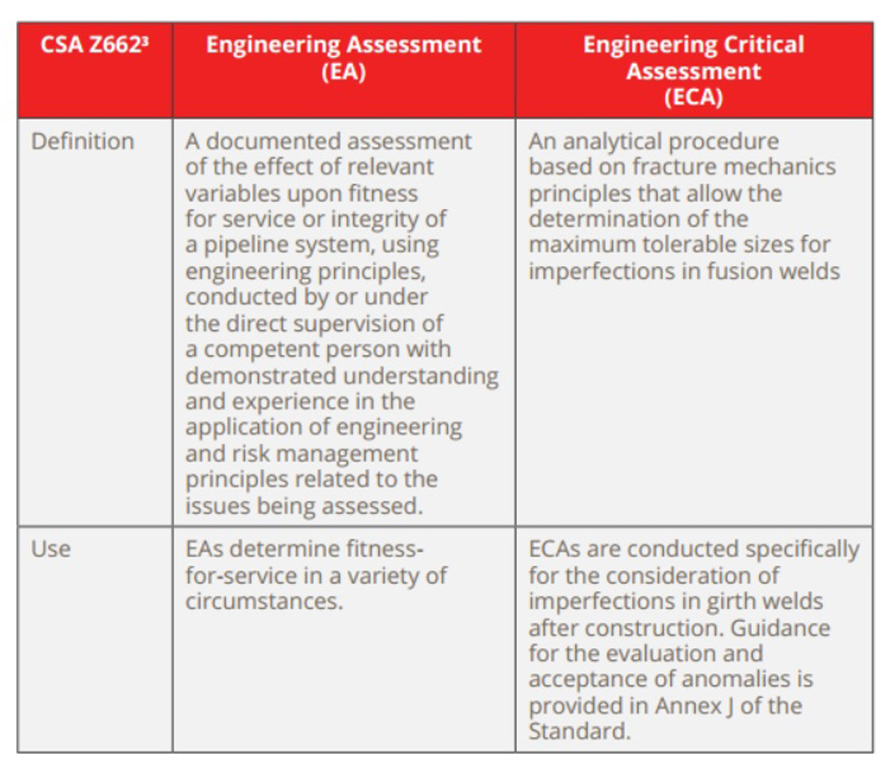
Both EA and ECA have defined terms in the Canadian Standard (CSA) Z662, adopted by the Canadian Energy Regulator Onshore Pipeline Regulations (SOR/99-294).2 CSA distinguishes EA from ECA (Table 1).
The United States pipeline safety federal regulations do not specifically define the term Engineering Assessment; however, Engineering Critical Assessment is defined in the natural gas transportation safety regulations in 49 CFR, Part 192.34 and is referenced in Subpart L – Operations Sections 192.625 and 192.6326.
This addition to the existing pipeline safety regulations as part of RIN 2137-AE72 Final Rule8, commonly referred to as the “Gas Mega Rule,” the Pipeline Hazardous Materials Safety Administration (PHMSA) established new MAOP reconfirmation requirements through a choice of six methods. One of the specified methods is ECA analysis.
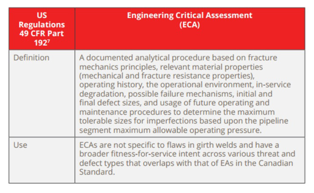
The related hazardous liquid pipeline safety regulations in 49 CFR Part 1959 do not explicitly define EA or ECAs.
However, engineering analysis, as related to pipes susceptible to longitudinal seam failures are mentioned in 49 CFR Part 195.303(d)10 as a risk-based alternative to pressure testing older hazardous liquid and carbon dioxide pipelines. This clause requires consideration of steel mechanical properties, including fracture toughness, similar to that of Canadian ECAs.
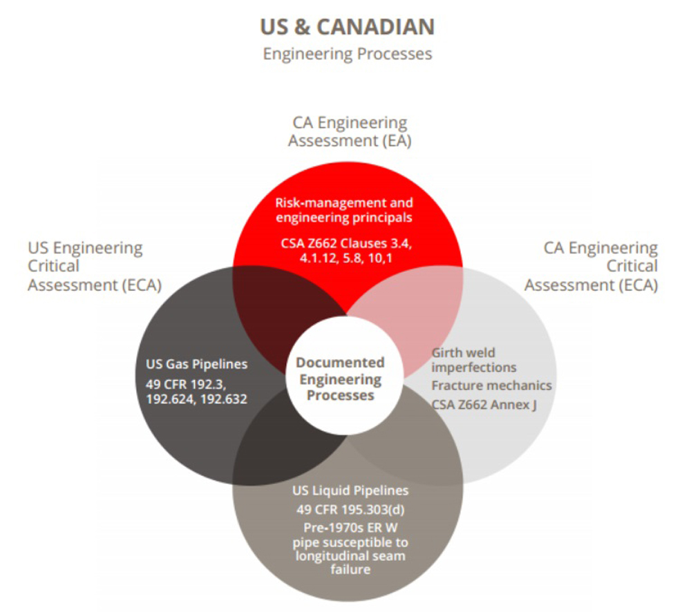
Figure 1 summarizes the convergencies in the four terms discussed above, related to the documented engineering procedures discussed above from the U.S. and Canadian regulatory compliance perspective.
In addition to the federal pipeline safety regulations in the US and the standard incorporated by reference in Canada, industry standards and guidance bodies have discussed engineering assessments in various documents to provide pipeline operators guidance for the safe operation of assets.
The American Petroleum Institute (API) maintains a robust standard detailing the fitness-for-service (FFS) methodology in API 57911. FFS assessment12 is defined as a methodology whereby flaws or a damaged state in a component is evaluated to determine the adequacy of the component for continued operation. API 579 Part 2 details an eight-step procedure to determine the FFS of a component organized by flaw type and damage mechanism13. When fracture mechanics is considered, damage mechanisms like brittle fracture, crack-like features, corrosion, and other damage, align with the CSA Z662 ECA principles.
The API 579 FFS assessment procedures cover both the present integrity of the component given a current state of damage and the projected remaining life. Qualitative and quantitative guidance for establishing remaining life and in-service margins for the continued operation of the equipment are provided in regard to future operating conditions and environmental compatibility.
Another standard API 110414, Welding of Pipelines, details analysis to determine weld-specific fitness-for-purpose criteria. The terms ECA and fitness-for-service are used interchangeably in this standard. Similar to Canadian ECAs, additional qualification tests, stress analysis, and inspection are essential under this standard.
The American Society of Mechanical Engineers standard B31.8S, Managing System Integrity of Gas Pipelines15, identifies ECA as suitable for threat prevention and repair method for certain instances of internal corrosion, external corrosion, stress corrosion cracking, girth weld defects, third-party damage, manufacturing, and construction threat disposition.
Beyond federal regulations and industry standards organizations, several organizations have mentioned EAs in their reports. Two notable industry reports include the International Natural Gas Association of America (INGAA) Fatigue Considerations report16 and the Pipeline Research Council International (PRCI) report on Fatigue Life Assessment of Dents17. Both reports detail fracture mechanics-based calculations and assessments for flaws to determine the fitness for service using ECA principles.
Requirements
In Canada, the requirements for engineering assessments are provided in Clauses 3.4, 4.1.12, 5.8 and 10.1 of CSA Z662.
Clause 3.4 establishes the structural requirements for the engineering assessment; Clause 4.1.12 outlines the considerations for pipeline design; Clause 5.8 outlines the considerations for material qualification, and Clause 10.1 provides the detailed elements that need consideration as applicable. It is noted that there is an opportunity to focus the EA as applicable to a specific threat or circumstance, but there is also a requirement to consider risk assessment as part of the analysis18.
In the US, Operators that chose to conduct an MAOP reconfirmation under 49 CFR Part 192.624(c)(3) “Method 3” using an ECA to establish the material strength and MAOP of the pipeline segment must assess: Threats; loadings and
operational circumstances relevant to those threats, including along the pipeline right-of-way; outcomes of the threat assessment; relevant mechanical and fracture properties; in-service degradation or failure processes; and initial and final defect size relevance. The ECA must quantify the interacting effects of threats on any defect in the pipeline15.
Beyond evaluating the material properties required for the U.S. ECA analysis, the documented records of material properties considered in such an analysis to reconfirm the MAOP must be traceable, verifiable, and complete (TVC) records. If the records for material properties used in the ECA are not TVC, the operators of gas transmission pipelines in the US must then adhere to the verification testing stipulations in 49 CFR 192.607(a)19.
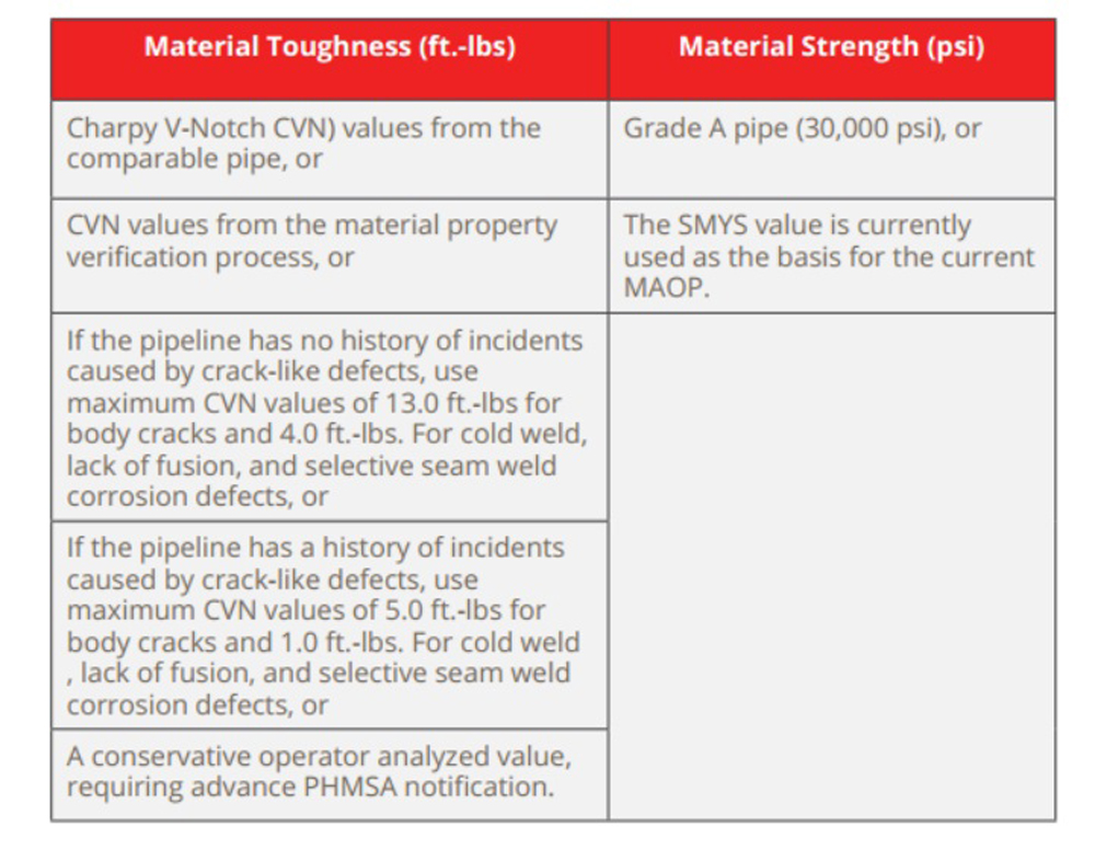
Until documented material properties are available, the federal pipeline safety code stipulates gas transmission pipeline operators are to use conservative assumptions (Table 3) for material toughness20 and strength21 values while conducting predicted failure pressure analysis reviews by a subject matter expert for corrosion metal loss and crack-like defects in accordance with 49 CFR 192.712.
Applications
In this paper, the general term engineering assessment (EA) will signify a documented process of analysis for a variety of pipeline integrity purposes. Specific regulatory requirements for a given asset must always be considered based on the jurisdiction of the individual asset and any applicable regulations.
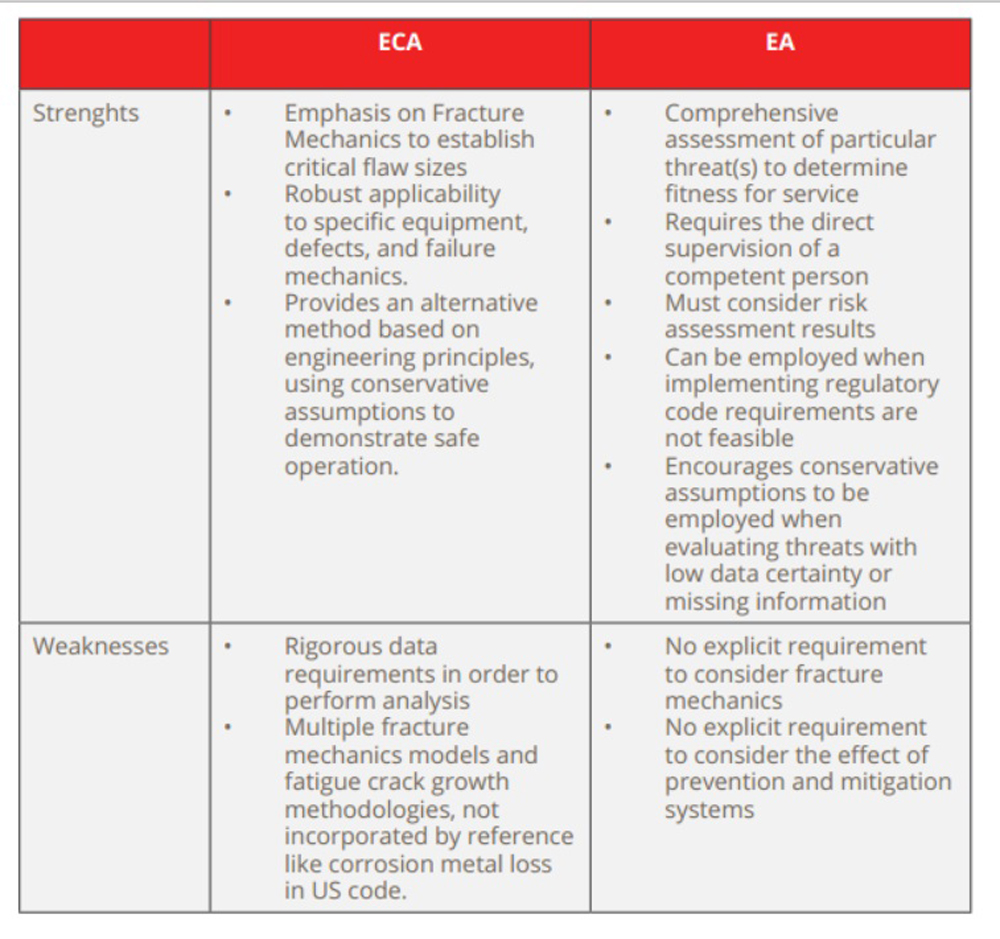
To develop an EA methodology applicable to assets outside of a particular geographic location, the strengths and weaknesses of each method are considered in Table 4.
In summary, ECAs are rigorous in applying fracture mechanics to determine flaw size but have limited applications. EAs, while more broadly applicable to various
threats and risks to the operation of pipeline systems, lack the formal requirements and process of ECAs. Competent engineers and robust data are required in all instances.
EAs for pipelines located in Canada are employed under the following circumstances:
- Class location designation changes
- Pipeline design
- Licensed/approved MAOP upgrade
- Defect assessment or evaluation of damage
- Change in operating conditions (product type, flow direction)
- Return to service of a pipeline after an outage
- Valve location and spacing
- Safety and reliability case management
- Reactivation after a failure
- Fitness for service of pipeline or implemented repair
- Establishing safety requirements for deviation from code requirements
In the United States, ECAs have been incorporated into the federal Code 22 explicitly for the following circumstances:
- § 192.624 MAOP reconfirmation
- § 192.632 ECA for MAOP reconfirmation
Other sections of the US pipeline safety regulatory code23 implicitly allow for EAs by using sound engineering principles or when calling for subject matter expert analysis related to:
- § 192.8 onshore gas gathering and regulated pipeline
- determination
- § 192.9 alternative deadlines for Type C gathering
- pipeline requirements
- § 192.179 gas transmission line valves
- § 192.506 gas transmission lines: spike hydrostatic
- pressure test
- § 192.607 Material verification
- § 192.619 MAOP for steel or plastic pipelines
- § 192.634 gas transmission line rupture mitigation valves
- § 192.636 gas transmission rupture responses
- § 192.710 gas transmission lines: assessments outside of HCAs
- § 192.712 gas transmission pipeline analysis of predicted failure pressure
- § 192.745 gas transmission valve maintenance
- § 192.921 gas line pipe baseline assessment
- § 192.937 gas pipeline integrity continual process
- of evaluation using MAOP reconfirmation as a reassessment option
- §193.2007 Definitions for “determine” based on sound engineering judgment as pertaining to LNG code
- § 195.303(d) liquid pipe regulations related to engineering analysis of pre-1970s ERW pipe
- §195.452(b)(6)(ii)) other risk-based alternative practice for liquid pipeline integrity management in HCAs
- §190.341 special permits
Outstanding PHMSA notice of proposed rulemaking (NPRM) indicates ECAs are being considered for changes in gas class location24.
Proposed Methodology
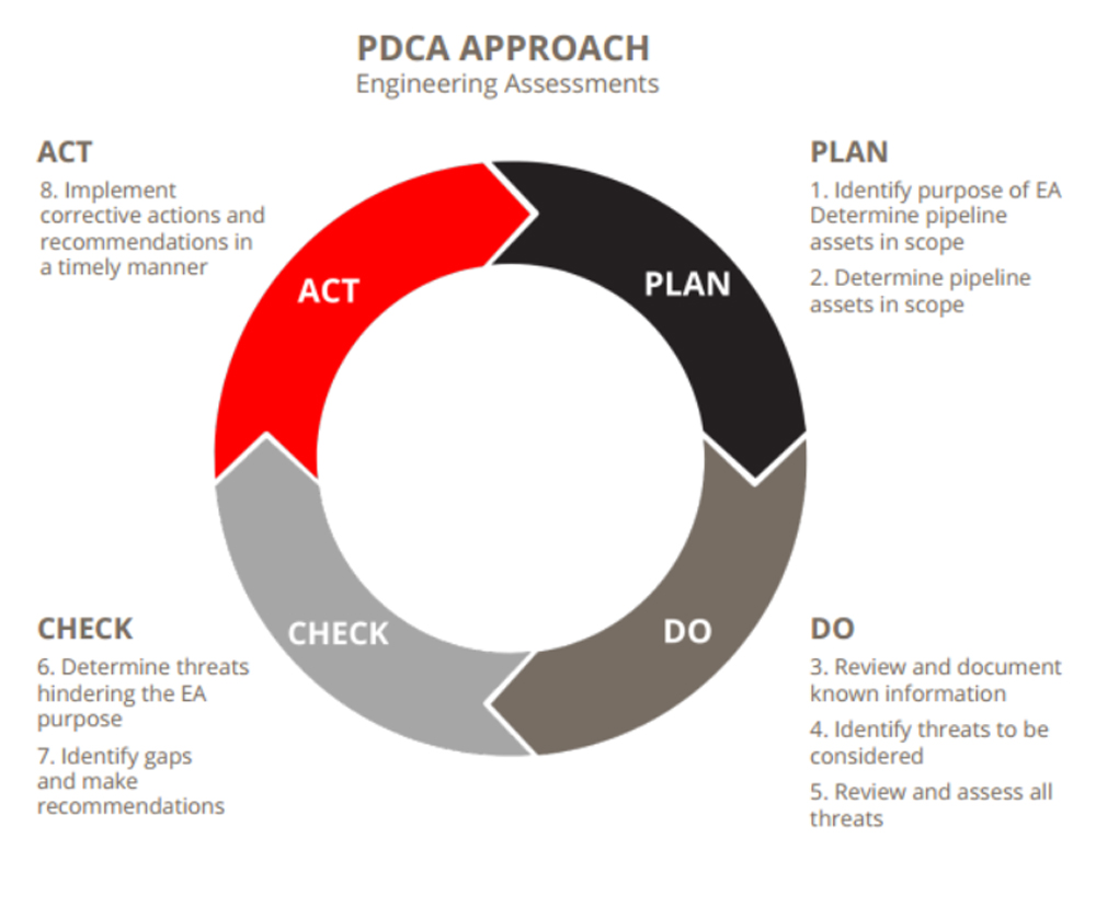
The proposed approach for EAs and ECAs follows a process that reflects the plan-to-do-check-act (PDCA) approach25. This approach is well established in the safety management systems literature applied to pipeline integrity management. The proposed approach is similar to the four-step process described in external26 or internal corrosion direct assessments27 and the eight-step FFS process outlined in API 57928.
Plan
- Identify the purpose of the EA
- Determine the pipeline assets that are within the scope of the EA
Do
- Review and document known information, including historical inspections
- Identify the integrity threats considered within the scope
- For each threat, review and assess:
- Inspection data
- Threat management program data
- (including prevention and mitigation
- systems)
- Operational, incident, and failure history
- Direct assessment data
- Risk assessment data
Check
- Determine whether each threat hinders accomplishing the purpose of the EA based on the information assessed
- Identify any gaps and make the necessary recommendations to fulfil the purpose of the EA
Act
- Implement corrective actions and recommendations in a timely manner
Figure 2 provides a simple visualization of the suggested EA approach overlaid with the PDCA cycle. Determining the purpose of the EA provides the foundation for the specific analysis considerations employed in subsequent steps. It is important to note, as will be demonstrated in the following case study, that available fracture mechanics modeling techniques common to Canadian ECAs and the API 579 FFS guidance may be used in step five when threats are assessed as the specific EA warrants.
The suggested model for conducting an EA must be led by a competent and qualified engineer who considers pertinent information and makes conservative assumptions in the absence of documentation.
Information Requirements
Regardless of jurisdictional determination or a specific type of EA delineation, for general FFS purposes, collection and consideration of system-specific information while conducting an assessment is essential. A competent and qualified engineer should consider, at a minimum, the pipeline system operational considerations, properties, threat assessments, risk assessments, inspections and repairs while conducting an EA.
Case Study
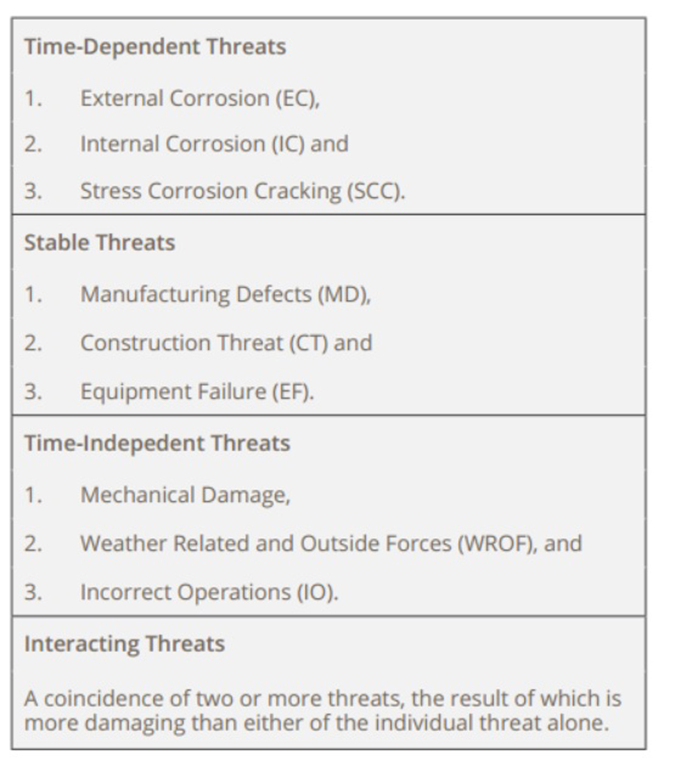
To demonstrate the EA approach, let’s consider the fitness for service of a discontinued NPS 8 natural gas pipeline that is to be returned to service. Within this EA, the threats listed in Table 6 by ASME B31.8S were evaluated along with the most recent semi-quantitative risk assessment results.
The proposed PDCA EC methodology is applied to this case study showing how the threat-based EA was overlaid with the semi-quantitative risk algorithm to yield a sound, engineering basis for reactivation.
1.6.1 Plan
When initiating the EA, proper planning is essential to ensure adequate analysis is performed. The purpose of this specific case study EA was to determine the FFS to reactivate a single pipeline asset. Beyond comparing inspection feature lists and repair documentation, a concerted effort to ensure the known failure mechanism behind the historical failures was being robustly evaluated.
Additional data surrounding the geohazard threat was a significant portion of the document request.
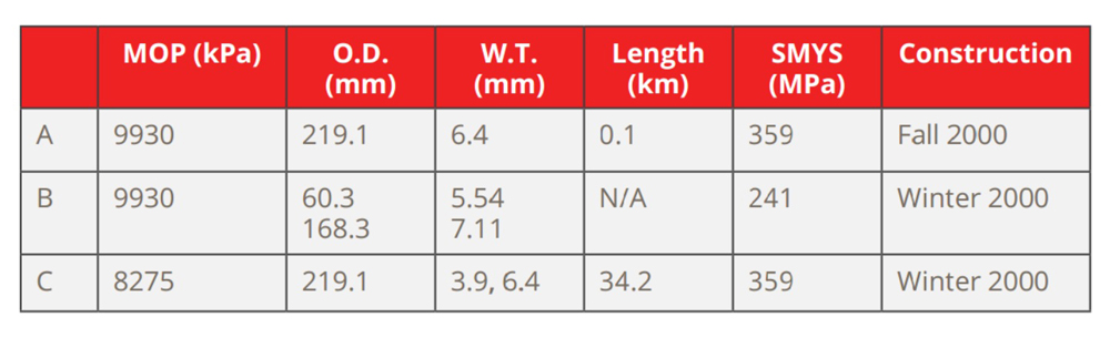
The segments comprising the asset of the study are summarized (Table 5). Another challenge with this pipeline was the presence of two short sections of unpiggable piping. We made sure to review the hydrostatic pressure test information as well as other wall thickness readings on these non piggable segments.
1.6.2 Do
All threats prescribed by ASME B31.8S, including interacting threats, were considered and reviewed (Table 6).
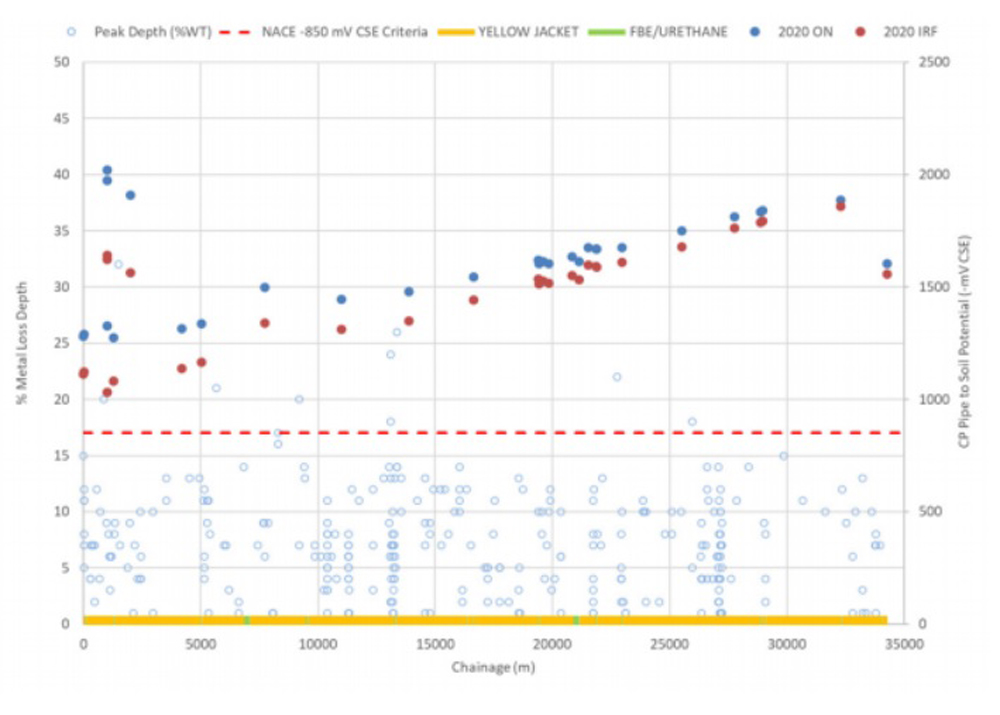
Let’s walk through the evaluation process for the threat of external corrosion. The effectiveness of the existing prevention and mitigation systems, such as external coatings and cathodic protection, was evaluated with in-line inspection (ILI) results along the mainline to determine the severity of the threat.
Figure 3 demonstrates the existing prevention and mitigation systems effectively manage the threat of external corrosion from the scarcity of external metal loss anomalies reported in the ILI.
Additionally, proximity to AC powerlines was also considered for this threat due to their adverse effect and increased risk of localized accelerated corrosion and threat to worker safety. Publicly sourced spatial data29 revealed three AC powerlines within 50 km of the in-scope pipelines.
However, CP data and ILI results did not reveal any cause for concern.
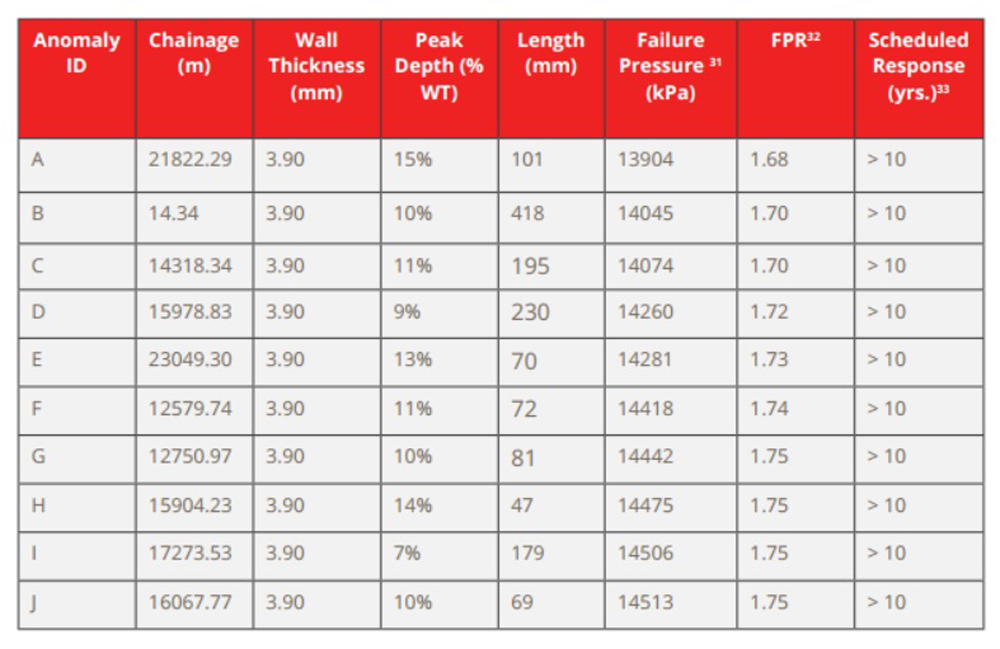
The line of the EA had multiple prior inspections using various magnetic flux leakage and geometry ILI technologies. After considering the repair history of addressed defects, the remaining anomalies calculated failure pressures using the ASME Modified B31G method30 were evaluated to ensure fitness for reactivation.
Table 7 provides a summary of the external metal loss anomalies remaining. The scheduled response for all the reported external metal loss anomalies was calculated using the approach described in ASME B31.8S to determine the remaining life and internal inspection after the pipeline was reactivated. This calculation revealed a minimum response time of greater than 10 years, which confirmed no immediate corrective action was required for this threat before the resumption of service.
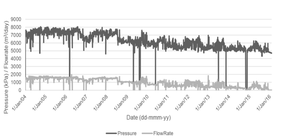
To evaluate the effect of pressure cycles as covered by the manufacturing threat, historical operational data was plotted for a twelve-year period and compared to cycling patterns in TTO Number 534. Figure 4 indicates the historical pressure and flowrate of the pipeline, which did not meet the criteria for aggressive pressure cycling.
Additionally, industry guidance in ASME B31.8S and other reports35 were considered for gas pipelines which historically have not been significantly affected by pressure cycling due to the compressible nature of gas and a limited number of cycles.
Lastly, as manufacturing is a stable threat with potential defects present during the pre-commissioning pressure test, any small, survivable features remaining after the successful hydrostatic pressure test would be resident, non-injurious features.
The primary threat of geotechnical outside force was evaluated through a review of additional pertinent data, including ground stability slope inclinometer surveys, an asset-specific geotechnical report following landslide activity, a company damage prevention management program, and recent HDD remediation activity to circumvent an active fault line, was reviewed. These preventatives and mitigative measures were deemed adequate to manage the threat of outside geotechnical forces.
The other five threats not discussed in this paper and interacting threats were evaluated based on industry guidance and information available by competent and qualified engineers.
The sound engineering practices employed and asset-specific analysis conducted on a threat basis were documented in the EA report. The report was peer-reviewed and accepted before delivery to the asset operator.
1.6.3 Check
During the EA review, adequate data was provided to determine FFS, and no threats were identified as unmitigated that could hinder the EA’s purpose of reactivating the asset. Assumptions were documented, and recommendations were provided in the final report.
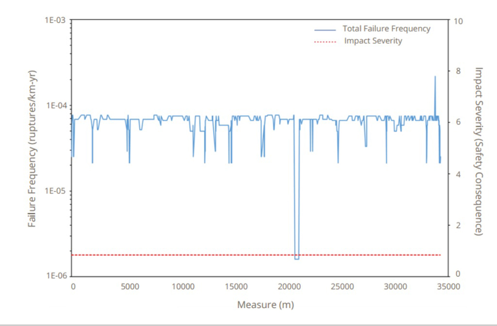
As an additional check of the desktop engineering assessment conducted, risk results were also evaluated by calculating the failure frequencies for all threats based on available information and a semi-quantitative risk model. For this pipeline, the risk results identified third-party mechanical damage as the major driver, with failure frequencies at all points except one being below 10-4 ruptures/km-year (Figure 5).
The drastic dip in failure frequencies near the 21,000 m chainage is from a newly replaced HDD section of pipe. The risk algorithm yielded third-party damage as the major driver based on the depth of cover for the specific pipeline, though the actual pipeline depth met or exceeded the regulatory requirements for cover across the length of the pipeline.
As the HDD remediation was performed before the risk results were calculated, outside forces were not a driving threat.
The engineers working on the desktop EA as well as those responsible for the semi-quantitative risk assessment, agreed the separate perspectives of threat-based assessment vs. the computational risk assessment provided a comprehensive and independent evaluation of the asset’s state of integrity. This complete review instilled integrity assurance in the resulting reactivation of the asset system.
Not necessarily an objective of the specific EA scope, but a consideration is the financial savings of performing a robust and sound engineering assessment to determine reactivation FFS instead of running another non-destructive pipeline ILI or other assessment. As the pipeline in question was out of service at the time of the EA, significant costs to perform an assessment would be incurred if this method were selected.
1.6.3 Act
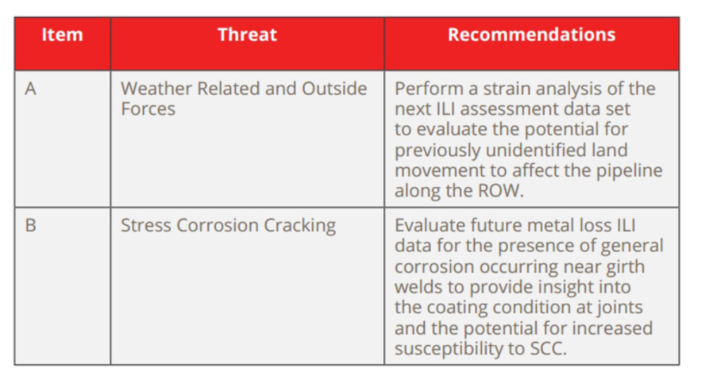
Based on the threat-guided EA and the computational risk results, the pipeline was determined fit to resume service.
Two recommendations, summarized by threat in Table 8, were suggested following the EA to maintain the asset’s integrity over the remaining operational life.
Conclusions
The proposed methodology and the associated case study demonstrate the effectiveness of employing a robust and comprehensive approach to EAs or ECAs to determine fitness for service. The proposed approach employs the strengths of both EAs and ECAs, namely the incorporation of threat analysis, risk assessment results, and fracture mechanics to provide pipeline operators with objective and technically sound results and tailored recommendations.
Additionally, in circumstances where no data or low confidence data is available, the involvement of one or more subject matter experts or competent engineers to conduct the EA or ECA using conservative assumptions is invaluable.
Authors: Parth Iyer is a senior integrity engineer at Dynamic Risk and a licensed professional engineer in Canada with over 10 years of pipeline integrity experience. He has an excellent understanding of pipeline integrity management programs, risk assessments, in-line inspections, regulatory audits and integrity data management.
Cassandra K. Moody is a professional engineer with 14 years of pipeline experience encompassing integrity management program (IMP) responsibilities in addition to serving in regional operations engineering capacities. Moody leads technical teams and provides subject matter expertise in program management, operations, safety management systems, threat assessment and change management principles.
References:
1 Canadian Standards Association (CSA) Z662: Oil and Gas Pipeline Systems,
Eighth Edition, 2019
2 Canadian Energy Regulator Onshore Pipeline Regulations (SOR/99-294), 2022-09-27
3 CSA Z662: Oil and Gas Pipeline Systems, Eighth Edition, 2019
4 49 CFR Part 192.3: Definitions
5 49 CFR Part 192.624, MAOP reconfirmation: onshore steel gas transmission
pipelines
6 49 CFR Part 192.632, ECA for MAOP Reconfirmation
7 49 CFR Part 192.3: Definitions
8 Federal Register A Rule by PHMSA on 10/01/2019
9 49 CFR Part 195 - Transportation of Hazardous Liquids by Pipeline
10 49 CFR Part 195.303(d), Risk-based alternatives
11 American Petroleum Institute (API) 579 Fitness for Service Standard, December 2021
12 API 579 page 54 1A.32
13 API 579 Flaw and Damage Assessment Procedures Table 2.1, page 76
14 API 1104 Welding of Pipelines, 22nd Edition, 2021, Annex A page 121
15 American Society of Mechanical Engineers (ASME) B31.8S Managing System Integrity of Gas Pipelines, 2018, Table 7.1-1 page 35
16 INGAA Fatigue Considerations for Natural Gas Transmission Pipelines, June 30, 2016
17 PRCI Fatigue Life Assessment of Dents with and without Interacting Features, PR-214-114500-R01, December 20, 2018
18 “Engineering Assessments in Support of Pipeline Safety – Emerging Trends and Approaches,” B. Mittelstadt; D. Williams, Pipeline Pigging and Integrity Management Conference, February 2022
19 49 CFR 192.607 Verification of Pipeline Material Properties and Attributes: onshore steel gas transmission pipelines, Paragraph C.
20 49 CFR 192.712 (i) Material toughness assumptions for US gas transmission operators
21 49 CFR 192.712 (ii) Material strength assumptions for US gas transmission operators
22 Title 49 CFR part 192
23 Title 49 CFR parts 192, 193, and 195.
24 Federal Register, Notice of Proposed Rulemaking RIN 2137-AF29, October 14, 2020, https://www.phmsa.dot.gov/regulations/federal-register-documents/2020-19872
25 API RP 1173 “Pipeline Safety Management Systems”
26 AMPP SP 0502 “External Corrosion Direct Assessment Methodology”, 2010
27 AMPP SP0206 “Dry-gas Internal Corrosion Direct Assessment”, 2006
28 API RP 579 “Fitness for Service Assessments,”2021 *** this was referenced
earlier. No need to footnote again.
29 “Topographic Data of Canada - CanVec Series,” Government of Canada,
2017 (https://open.canada.ca/data/en/dataset/8ba2aa2a-7bb9-4448-b4d7-f164409fe056 )
30 American Society of Mechanical Engineers, Manual for Determining the
Remaining Strength of Corroded Pipelines, ASME
31 Failure Pressure is the calculated burst pressure of the pipeline with a safety
factor
32 Failure Pressure is the calculated burst pressure of the pipeline with a safety
factor
33 Failure Pressure Ratio, the burst pressure divided by the MAOP
34 “Figure 7.2.1-1: Timing for Scheduled Responses: Time-Dependent Threats,
Prescriptive Integrity Management Plan,” ASME B31.8S Managing System
Integrity of Gas Pipelines, 2020
35 TTO Number 5, “Integrity Management Program Delivery Order DTRS56-02-D-70036,” Department of Transportation Research and Special Programs
Administration Office of Pipeline Safety, October 2003
36 J. Keifner and M.J. Rosenfield, GRI Report GRI-04/0178, “Effects of Pressure
Cycles on Gas Pipelines,” September 2004
Presented at the 35th Pipeline Pigging & Integrity Management Conference, February 2023. Copyright 2023 Clarion Technical Conferences and the authors.

Comments