June 2023, Vol. 250, No. 6
Features
Proactive Integrity Management for Pipeline River Crossings
By James Bainbridge, Senior Engineer, ROSEN Canada
(P&GJ) — The selection of appropriate pipeline routes is critical for reducing the impact of geotechnical and hydrotechnical hazards. Many hazards, including water crossings, can be avoided by careful route planning.
However, sometimes terrain dictates that they must be faced head on. Onshore pipelines are designed to be fixed and stable but are frequently located within dynamic river, floodplain and coastal environments, which can pose a challenge to operators when maintaining pipeline integrity.
Rivers are forever in flux; channel movements can be vertical (scour and degradation/aggradation), horizontal (bank erosion and encroachment), and full channel path movements (avulsion and meander cutoffs). These processes can occur gradually, or rapidly within periods of high river flow or flood events, and where avulsions occur.
Intense precipitation or melting snow can cause increased riverbed erosion, general scour and local scour, which occurs when the forces from the river flow acting on a sediment particle exceed the stabilizing forces.
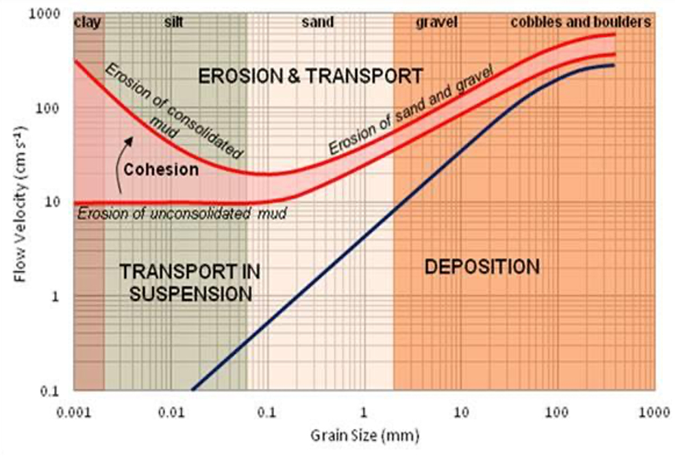
The Hjulström curve (Figure 1) can be used to determine whether a river will erode, transport, or deposit sediment, dependent on the particle size and flow velocity. The removal of sediment from the bed or banks of a watercourse can result in exposure of the pipeline, which could ultimately result in unsupported pipeline spans within the crossing.
Vintage gas and liquid pipelines were typically constructed using open-cut trenching methods at river crossings, which may have resulted in shallower or more variable cover depths than modern horizontal directional drilling (HDD) techniques.
Since open-cut trenching is typically shallower than HDD it can result in pipelines being installed within the mobile bed of a river, rendering them susceptible to scour, even at cover depths that are within industry specifications. This issue may still arise for HDD installations; however, is less likely for well-designed crossings that take account of scour behavior.
Buoyancy control at river crossings is typically addressed in the design phase, and controlled by an increase in wall thickness, concrete coating, or installation of saddle weights. However, inadequate control measures, or degradation of coatings and saddle weights can increase susceptibility to buoyancy.
Pipelines that are exposed and spanning in water currents will experience hydrodynamic loading and potentially vortex-induced vibrations (VIV). If the span length and the current velocity are sufficiently high, the pipeline is at risk of structural overload or accumulating fatigue damage.
Floodwater and high current velocities can transport ice and large debris, which can result in impact loading on exposed pipelines. The likelihood of third-party damage from boats, anchors or dredging also increases at river crossings with exposed pipe.
Global temperatures are on the rise, and with that comes the potential for intensification of the hydrological cycle, leading to an increased magnitude and frequency of precipitation events. This is expected to have a significant effect on the prevalence of pipeline integrity threats at water crossings.
This pipeline integrity threat at river crossings is a worldwide issue, from the tropical mountain ranges of the Amazon Rainforest to desert wadis, and the over-steepened river valleys of the North American Interior Plains.
Pipeline Management
Pipeline operators have a number of tools at their disposal to assist in the identification of potential exposures and free spans at river crossings, and to predict “high-risk” areas that are most susceptible to erosional processes.
There is a range of literature available relating to pipelines in water crossings, including CEPA documents Pipeline Associated Watercourse Crossings1 and API RP 11332.
These apply to new and existing hydrocarbon pipelines and provide a process for the identification, assessment and management of risks to pipeline integrity associated with hydrotechnical hazards.
Identification
- Crossing Surveys – Depending on the jurisdiction under which a pipeline is operated, river crossing surveys are mandated at defined intervals. Crossing surveys provide the cover depth to the pipe crown but will also provide the riverbed profile.
However, surveys only provide data for a brief snapshot in time and depending on the energy and dynamicity of a fluvial system, erosion and deposition at the pipe crossing may be continually changing. In highly dynamic systems, pipelines can become exposed and re-covered within a matter of hours.
Multiple channels may be present at braided and anastomosing river crossings, potentially increasing the risk of newly developing pipeline exposures. The comparison of historical surveys is an excellent method to better understand riverbed morphology, predict potential channel erosion or migration, and to assess the fluvial threats to the pipeline.
- Site Surveys – Field inspection by a geohazard specialist will characterize the geomorphological, hydrotechnical/geotechnical factors that influence the severity of hydrotechnical hazard types.
This information is essential for the evaluation of the integrity threat to pipelines, and to provide representative inputs into any subsequent modelling that may be performed, whether scour predictions or hydrodynamic and VIV loading assessments. It is critical to be able to identify additional information pertinent to the crossing that could affect the likelihood of an increased risk, such as nearby civil works within or near to the river crossing, or infrastructure close to the crossing (bridges, other operator’s pipelines, weirs).
The horizontal distance from the pipeline vertical overbends to the channel banks should be confirmed and an assessment of channel migration patterns performed to predict the potential for sections of the pipeline being affected that were not originally considered within the crossing location design.
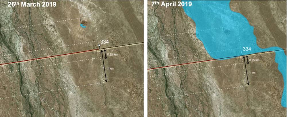
Evaluation of aerial imagery can be performed to determine lateral migration. Where lateral channel migration is high, problems of exposure can arise. An example of rapid lateral channel migration that has taken place over 15 years (Figure 3).
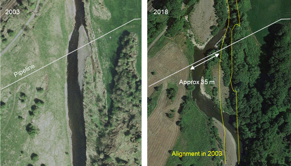
The rate of movement exceeds 2 m per year and the distance of migration is approximately three times the channel width. As a consequence of the erosion, the pipeline section that was previously routed across the flood plain adjacent to the crossing became exposed in the riverbed.
Current flow velocity has a significant effect on acceptable span lengths within river crossings. This data can be obtained by direct measurement. However, it is more typically based on computational flow velocity models.
- In-Line Inspection – Using inertial mapping units (IMU) within an in-line inspection (ILI) can identify the presence of pipeline bending strain at river crossings, and if historical inspection data is available, pipeline movement assessments can be performed to establish any displacement of the pipeline.
Evidence of pipeline exposure or spanning may manifest as vertical upward displacement in the IMU data, which is potential evidence of buoyancy, or downward displacement if the pipe is spanning and settlement has occurred. Horizontal out-of-straightness in the direction of river flow is also a potential indicator that a pipeline is spanning.
If an ILI is armed with a caliper tool, deformation anomalies detected on the upstream side of the pipe circumference can be indicative of impact loading from debris. Axial stress/strain tools are a newer technology to the market, which can be combined with bending strain analysis using IMU for a complete determination of longitudinal stress/strain for management of pipeline movement and geohazards.
Assessment
- Scour Computation – Several methods exist which can be used for predicting the degradation (i.e. lateral and vertical scour rate and extent) of water channels (e.g. USBR3 and NEH4).
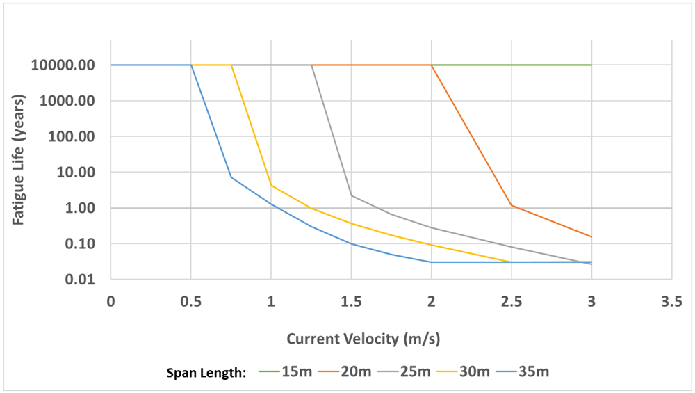
- Span Assessment – structural analysis can be performed to establish the span length at which a pipeline is susceptible to excessive loads or damage from hydrodynamic loading and VIV for a specific river crossing. The method detailed in DNVGL-RP-F105 can be used to assess the dynamic response of pipeline free spans due to current loading.
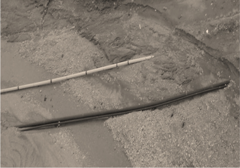
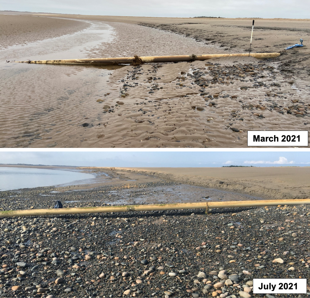
An example of a free span that has developed in a dynamic estuary crossing environment (Figure 4) and the associated span assessment predicting how fatigue life resulting from VIV is affected by current velocity (Figure 5).
- Current Flow Velocity Modeling – a key requirement of the assessment of exposed pipeline crossing is to understand the current flow velocity at the crossing location. If direct measurement data (gauging stations) is not available for the site, a comparison with similar catchment characteristics may be suitable or selection of an empirical method.
An empirical “rational method” predicts the maximum discharge for a location based on rainfall intensity and size of the drainage area. An empirical method using channel properties may also be used, such as the Chezy method5, which derives flow velocity and discharge rate based on flow resistance factors and channel characteristics.
- Flood Risk Modelling and Mapping – flood risk models can be developed to support prioritization of ‘at risk’ crossing locations. Geographic Information Systems (GIS) with spatial analysis functions can process a range of datasets to model flood risk for a pipeline network.
An example of flood migration mapping from the spring thaw in Kazakhstan, demonstrating how it overtops an embankment parallel to the pipeline easement (Figure 5).
Management
Hydrodynamic hazards can be managed by reducing the likelihood of failure, which can be operational or engineered controls. Operational controls can reduce the risk associated with pipe failure and engineered controls reduce the probability of failure.
Operational Controls
- Aerial Monitoring – remote sensing technology such as LiDAR or photogrammetry via aerial patrols can be used to assess channel migration and bank erosion. Comparison of InSAR data can detect ground movements and flood extent in certain environments.
- Ground-based monitoring – repeat river crossing surveys allow for the assessment of changes in the depth of cover, the presence/extent of scour and the development of pipeline exposures.
- Pressure reduction – reducing operational loads within the pipeline at river crossing locations will reduce secondary stresses at bends.
- Use of IMU/caliper to detect any profile or strain changes that could be linked to current loading.
Engineered Controls
- River channel maintenance, including bank protection, current deflectors, dredging, and conserving pools and riffles.
- Repairs – reburial of the pipeline using open cut trenching.
- Erosion defense – concrete mattresses, frond mats (subject to particle size), grout bags, rock and gravel dumping (e.g. rip-rap), channel bed armoring.
- Vortex suppression device – VIV suppression devices such as helical strakes or fairings can be installed at pipeline river crossings to reduce or eliminate the likelihood of ‘lock-in’ (close to the natural frequency of the pipe span) occurring if a pipeline free-span develops.
- Pipeline re-routing.
- Installation of isolation valves, allowing crossing section to be isolated during extreme events, or if a failure is suspected.
Conclusion
The threat to pipelines at water crossings is likely to increase as global warming continues to contribute toward the increased magnitude and frequency of precipitation and flood events.
There are many activities that operators can undertake to investigate and assess the risk of loading and damage to pipelines at river crossings. These include measurement of the pipeline depth of cover on the crossing and comparison with the predicted maximum scour depths.
Understanding whether the crossing is at a vulnerable location within the river system is an important first step in recognizing if protection activities are necessary.
The development of a hazard management program for pipeline crossings will help mitigate failures in ever changing river environments.
Comments