New Model Improves CO₂ Pipeline Fracture Control Beyond Charpy Tests
By Christoph Bosch, Senior Expert Materials, EUROPIPE
(P&GJ) — Pipelines are by far the most economical method for transporting large amounts of CO2 in the context of carbon capture, utilization and storage (CCUS). The transport of gaseous CO2 usually does not place any demands on the pipe material that go beyond the classic design if water drop-out is prevented.
However, the major challenge for line pipe steels when transporting CO2 in the liquid or dense phase is the requirement of high toughness in the base material to prevent running ductile fracture due to the delayed CO2 decompression behavior, which provides a constantly high crack-driving force. For such high toughness requirements, the CVN impact energy that is usually used to characterize the toughness of line pipe steels, becomes a parameter of questionable significance.
Therefore, an approach was developed based on a more suitable measure of toughness determined in instrumented drop-weight tear (DWT) tests instead of the CVN impact energy.
A DWT-based analytical model to predict arrest or propagation of running ductile fracture as an alternative to the CVN-based “Battelle Two Curve Model” is presented and compared to full-scale burst test results that have been performed in dense phase CO2. Ongoing optimization of the model is supported by “virtual” burst tests from a numerical model based on finite element simulation.
Systematic capture, utilization and storage of carbon dioxide (CCUS), originating from the demands of energy transition, will be a key topic in the future. In addition to other related technical and engineering issues, one challenge will be to provide suitable transportation options and capacities.
The major challenges for line pipe steels when transporting CO2 in the liquid or dense phase include the requirement of high toughness in the base material in order to prevent running ductile fracture due to the delayed CO2 decompression behaviour and, thus, a constantly high crack-driving force.
The decisive material property to ensure safety against running ductile fracture is a sufficient upper shelf material toughness. To date, the leading standards for design of pipelines for dense-phase CO2 service in terms of both geometry and toughness, ensuring ductile fracture arrest, are DNV-R-P F104 [1] and ISO 27913 [2].
Both comprise similar evaluation concepts for the arrest of running ductile fracture, which are based on a limited number of results of full-scale burst tests (FSBT) involving CO2 or CO2 mixtures in liquid phase carried out so far. The concepts come along with the adaptation of the well-known and empirically derived Battelle Two Curve (BTC) model established by Maxey et al. [3].
The adaptation is necessary to account for the characteristic delayed CO2 decompression behaviour with a pronounced saturation plateau [4]. The derivations have proven to be conservative, latest by Cosham et al. in [5]. Apart from the need for more test results, discussions arise whether high toughness requirements in terms of Charpy V-notch (CVN) impact energy (ECVN) exceeding 250 J are justified due to the limited significance of the test for high-toughness line pipe steels.
Here, CVN impact tests typically reveal non-broken specimens where bending, plastic deformation and friction dissipate a non-negligible proportion of impact energy [6].
Ductile Fracture
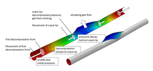
In a pipeline with a running fracture, two zones can be distinguished ahead of the crack tip in which the pressure regime of the medium is influenced in different ways (Figure 1). Starting from the crack tip, the first decompression front runs at acoustic velocity in the same direction than the propagating crack. Ahead of the decompression front the internal pressure remains unchanged at the initial pressure level (red color). Behind this front the internal pressure decreases up to the crack tip.
For the risk assessment of long-running ductile fracture (RDF), material toughness as a measure of resistance to fracture is commonly agreed. A semi-empirical model, the “Battelle Two Curve Model” (BTC model) was already developed in the early 1970s [3], [7], [8].
In this model, it is assumed that the specific impact energy in the Charpy impact test is directly proportional to the strain energy release rate that quantifies the energy released per unit area of newly created crack surface during fracture propagation. A formula for the transportation of lean natural gas was developed for the calculation. [3], [7], [8]. The model is still in use. However, empirical correction factors are used for modern and especially for high-strength line pipe steels.
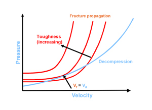
The application of the BTC model is shown schematically in Figure 2.
Figure 2 compares the decompression of the natural gas with the ductile fracture propagation velocity. If the crack propagates faster than the decompression, no fracture arrest occurs. In the case of faster decompression, the model predicts fracture arrest. The crack propagation velocity in turn depends on the resistance of the material to fracture propagation, which is described by the CVN impact strength.
The limit state is given when the fracture resistance and decompression curves meet at a tangential point, where the fracture resistance curve is represented by the required minimum toughness for fracture arrest. The BTC model can be used to predict fracture arrest for natural gas transportation in line pipes up to grade X70 and CVN impact energy requirements of approx. 200 to 250 J.
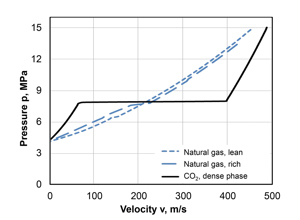
If the BTC model is also to be used for the prediction of fracture arrest for the transport of CO2 in the liquid or dense phase, it must be noted that CO2 decompression curves, due to the liquid-gas phase transition, show significant decompression retardation in comparison with natural gas, which are characterized by the formation of a plateau (Figure 3).
As a result, the application of the BTC model leads to higher demands on the CVN impact strength in the base material of the line pipe.
Formally, modern line pipe steels can meet requirements for high CVN impact energy up to approximately 400 J in the base material. However, incomplete fracture combined with significant deformation is frequently observed on impact specimens above approx. 200 to 250 J.
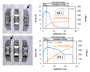
For non-broken specimens, a certain fraction of energy is dissipated by friction between the specimen and the bearings and plastic deformation and not by driving the crack. This is exemplified in Figure 4, showing non-broken CVN test specimens after testing, supplemented with force-deflection curves and derived impact energies. The energy curve of the specimen (Figure 4a), representing a moderate impact energy level of 150 J, shows a clear change in the gradient, which allows a good distinction of energy to be applied for fracture propagation (large proportion) and for bending (small proportion).
Figure 4b is typical of a high level of impact energy of 350 J and above. From the energy curve it is no longer possible to distinguish between energy required for fracture propagation or for bending. In this case, the high CVN impact energy no longer quantitatively describes the resistance of the material to fracture.
DNV Recommended Practice RP-F104:2021 [1] describes the procedure for assessing ductile fracture propagation using criteria for estimating limits for crack arrest based on full-scale burst tests. This is shown graphically as a plot of the normalized load Y against the normalized, CVN-based toughness X (Figure 5). X and Y are based on the BTC model and include as input variables the pressure P at the crack tip, the pipe outside diameter D or radius R, the pipe wall thickness t, the yield stress sf, the characteristic CVN energy RCVN and the modulus of elasticity.
Fracture arrest is expected for X-values of 25 or greater if the associated Y-values are on or below the limiting curve. The assessment in this area is based on laboratory tests. Fracture arrest is also possible for X values of less than 25. However, there is no database from full-scale tests for this range. This is why a specific assessment is required including the option to perform full-scale tests.
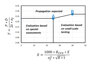
Of particular interest are the points A (X=25; Y=0.23) and B (X=40, Y=0.27) (Figure 5). Point A describes the minimum requirement for CVN energy and the wall thickness required for a pipe of a certain grade and outside diameter, while point B describes the minimum required wall thickness and the related minimum CVN energy.
The wall thicknesses and CVN energies determined for Points A and B are exemplified in Table 1 for X65/L450 grade line pipe with diameters ranging from 609.6 to 914.4 mm (24 to 36 inches). A CO2 saturation pressure of 70 bar was assumed. This value is achieved, for example, at a content of 6.0 % N2 in the CO2 and a temperature of 17°C [9]. The effect of variation of the grade and the CO2 saturation pressure is shown in Figure 6, considering X60 and X65, in line with DNV-RP-F104, and CO2 saturation pressures of 59 and 70 bar.
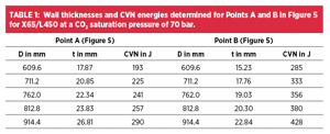
The results of the calculations shown in Table 1 and Figure 6 illustrate that within the area in which fracture arrest is to be expected, the use of pipe outside diameters of up to 32 inch is feasible when the normalized CVN-based toughness X is kept close to a value of 25 (Point A in Figure 5).
Optimizing the design in terms of minimizing the wall thickness (Point B in Figure 5) already leads to CVN minimum requirements much higher than 250 J and therefore with questionable quantitative significance already at the lowest considered pipe diameter of 24 inch.
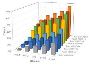
Within the limits of the DNV approach, compensating higher toughness by higher wall thickness is one possible approach. In this respect, ISO 27913 [2] is less restrictive and can be considered as an alternative.
Alternative Assessment
Given the fact that, as shown, the CVN impact energy can lead to incorrect estimation of material toughness, it seems reasonable to find a more suitable toughness measure or an alternative model approach. This was already considered when the BTC model was established [3] [7], [8].
It was suggested that the impact energy measured in instrumented drop-weight tear (DWT) tests was a more relevant and accurate measure of resistance than the CVN impact energy for pipe materials that exhibit higher toughness levels. [10] Comparison of the specific DWT impact energy to the CVN impact energy for various materials, as shown in Figure 7 [11] would support this approach. Up to an energy level of about 250 J, a linear correlation of CVN impact energy to DWTT impact energy is evident, showing an increased scatter in the higher range of data considered. Above a level of 250 J, scatter is predominant, and a trend cannot be derived with certainty.
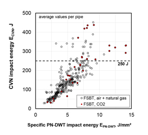
Based on the above observations, a modification of the BTC model was applied, in which the impact energy measured in instrumented DWT tests was selected as the measure of toughness. As a further modification, the fracture-mechanical toughness parameter J-integral was introduced, which is focused on the crack tip load of the running ductile fracture.
On a laboratory scale, instead of the usual DWT specimen with a pressed notch (PN-DWT), a fatigue pre-cracked specimen with an a/W ratio of 0.3 is used. In the DWT test, the impact energy is determined and converted to a toughness value based on the J-integral, designated J-DWT.
The toughness requirement for a given pipe geometry and a desired operating pressure of the pipe is determined in a limit state analysis analogous to the BTC model. Here the limit state is also represented when the crack resistance and decompression curves meet at a tangential point.
A detailed description of the assessment model can be found in the literature [12] and [13]. The calibration was based on a database with results from 38 full-scale burst tests (FSBT) of different pipe geometries, strengths and internal pressures. The toughness was determined in instrumented CVN and DWT tests for each of the test pipes in which either running fracture or fracture arrest could be observed.
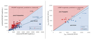
Figure 8 shows the predictions for arrest and running fracture based on the material toughness measured and evaluated by the modified BTC model. The prediction based on the J-DWT toughness measure is noticeably more accurate than based solely on the PN-DWT energy.
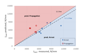
The full-scale tests considered in the modified BTC model include the publicly available results from 6 tests that were performed with dense-phase CO2. The model is therefore better calibrated for applications in which natural gas (lean and rich) is transported. However, as shown in Figure 9, the prediction for the CO2 full-scale tests is similarly successful as for the entirety of the full-scale tests and covers a pipe outside diameter (OD) range from 610 mm to 914 mm.
Numerical Model
Due to the limited number of full-scale burst tests available to date, and to support development and discussion of requirements related to the fracture behavior of pipes subjected to decompressing dense-phase CO2 content in the meantime, results of numerical simulations of “virtual burst tests” can help derive tendencies and provide bridging support.
To support the calibration of the modified BTC model to derive minimum required material toughness for ductile fracture arrest, a finite-element-based numerical simulation approach has been developed in parallel and was first reported in [14]. Within this numerical model, fracture toughness of the pipe material is represented by damage parameters that are also calibrated by use of pre-fatigued J-DWT specimens. Therefore, the experimental basis is the same for both the numerical as well as the analytical model, as discussed in [15].
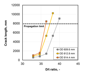
This basic numerical modeling approach was followed, and the model was adapted to the characteristics of pressurized CO2 [16]. With the validated model parameter studies and “virtual burst tests” are possible. This is exemplified for the calculation of crack lengths in a numerical parameter study, depending on D/t ratio and OD of a pipe of grade X65, an initial internal pressure of 127 bar and a CO2 saturation pressure of 72 bar. In the simulations, a critical crack length of 8 m was assumed to decide whether a running fracture was likely to propagate or to arrest (Figure 10).
Three typical tendencies were predicted, identified by:
- quick arrest with a crack length below 1.5 m up to a D/t ratio of 34.7;
- slow arrest with significantly increased crack lengths. At the D/t ratio of 36.4, the pipe with OD 813 mm showed slow arrest with significantly increased crack length below 6 m, whereas the pipe with OD 914 mm slightly exceeded the limit criterion of 8-m tolerable crack length;
- propagation clearly exceeding the criterion of 8 m tolerable crack length. At D/t ratio 38.0, the pipes with OD 813 and 914 mm did not show arrest, while D/t ratios of 40 and above achieved propagation for all pipe OD considered in the parameter study.
With respect to D/t the simulation results given in Figure 10 indicate that a limiting D/t ratio, above which running fracture is to be expected, is not constant for all pipe diameters, but shifts towards smaller D/t values with increasing OD.
Conclusions
Longitudinally welded large-diameter pipes are generally suitable for transporting CO2 if no aqueous phase is present in the transport medium and corrosion is therefore avoided. When transporting CO2 in the liquid or dense phase, the design requires significantly higher toughness of the line pipe base material in order to prevent ductile fracture propagation.
Since the CVN impact energy that is usually used to characterize the toughness of line pipe steels, becomes a parameter of questionable significance for those scenarios, an approach is shown that utilizes a more suitable measure of toughness and a model alternative to the CVN-based “Battelle Two Curve Model.”
This alternative model utilizes the toughness determined in instrumented drop-weight tear tests instead of the CVN impact energy. The prediction quality of the model is more accurate, when the energy measured on modified specimens with fatigue pre-crack (J-DWT) is used instead of the energy obtained from testing standard, pressed-notch type (PN-DWT) specimens.
The alternative model is under continuous optimization for the transport of CO2 in the dense phase. In this context “virtual burst tests” from an adapted numerical model, based on finite element simulation, are also considered.
Results from a numerical parameter study confirmed that that a limiting D/t ratio, above which running fracture is to be expected, shifts towards smaller D/t values with increasing OD. This is in line with the observation that, within the limits of current standards, requirements of higher toughness can be compensated by higher wall thickness.
References
[1] DNV Recommended Practice DNV-RP-F104, Edition February 2021, Amended September 2021, Det Norske Veritas, 2021.
[2] ISO 27913:2024: Carbon dioxide capture, transportation and geological storage – Pipeline transportation systems, ISO, Geneva, Switzerland, 2024.
[3] Maxey, W. A.: Fracture initiation, propagation and arrest, Pipeline Research Committee of the American Gas Association, 5th Symposium on Line Pipe Research, Houston, Texas, U.S.A. (1974)
[4] Michal, G., Østby, E., Davis, B., Røneid, S. & Lu, C. (2020). An Empirical Fracture Control Model for Dense-Phase CO2 Carrying Pipelines. ASME Paper No. IPC2020-9421
[5] Cosham, A.; Michal, G.; Østby, E.; Barnett, J.; The Decompressed Stress Level in Dense Phase Carbon Dioxide Full-Scale Fracture Propagation Tests, Proceedings of the 14th International Pipeline Conference, Paper IPC2022-86855 (2022), Calgary, Canada.
[6] Cosham, A.; Jones, D. G.; Leis, B. N.; Hopkins, P.; Barnett, J.: Not another Charpy V-Notch correction factor…? 6th International Pipeline Technology Conference (2013) paper S03-3, Ostend, Belgium
[7] Maxey, W. A.; Kiefner, J. F.; Eiber, R. J.; Duffy, A. R.: EXPERIMENTAL INVESTIGATION OF DUCTILE FRACTURES IN PIPING. Proceedings of the 12th World Gas Conference (1973) IGU/C 34-73, International Gas Union, Nice/FR.
[8] Maxey, W. A.; Kiefner, J. F.; Eiber, R. J.; Duffy, A. R.: Ductile Fracture Initiation, Propagation, and Arrest in Cylindrical Vessels. Proceedings of the 1971 National Symposium on Fracture Mechanics, Part II, STP514 (1971) pp. 70-81, Fig. 9, ASTM, Philadelphia/USA.
[9] Di Biagio, M., et al.: Requirements for safe and reliable CO2 transportation pipeline (SARCO2), Final report, 2017.
[10] Maxey, W. A.; Eiber, R. J.: Fractures in Pipeline – Main Influencing Factors. Proceedings of an International Seminar on Fracture in Gas Pipelines, Moscow, USSR (1984) pp. 49-81, CBMM, São Paulo/BR.
[11] Mondry, A.; Bosch, C.; Weil, C.; Brauer, H.; Mirkovic, D.: New Aspects on Fracture Resistance of Line Pipe Steels for the Transport of Carbon Dioxide in Dense-Phase. Proceedings of the 2025 Pipeline Technology Conference, May 05-08, Berlin, Germany.
[12] Golisch, G., Erdelen-Peppler, M., Mondry, A., Kalwa, C.: Toughness Assessment in Pipelines – a Novel Approach on the Arrest of Running Ductile Fracture, in Proc. Technology for Future and Ageing Pipelines Conf., Gent, Belgium, 2018.
[13] Golisch, G.; Kalwa, C.: Fracture control of natural gas and CO2 pipelines using modified DWT tests: 3R International, Technical journal for piping system integrity and efficiency, Special 01/2020.
[14] Völling, A.; Erdelen-Peppler, M.; Kalwa, C.; Brauer, H.; Ouaissa, B.; Meuser, H.: Numerical approach for crack-arrest prediction by FEM, Paper No. S19-01, in Proceedings of 6th International Pipeline Technology Conference, October 6-9, 2013, Ostend, Belgium.
[15] Völling, A.; Erdelen-Peppler, M.; Adequate toughness testing of linepipe steels for crack-arrest prediction, Paper No. S04-03, in Proceedings of 6th International Pipeline Technology Conference, October 6-9, 2013, Ostend, Belgium.
[16] Mondry, A.; Bosch, C.: New Aspects on Modeling Ductile Fracture Arrest Performance of Large-Diameter Pipes in Dense-Phase Carbon Dioxide, Paper No. 132853, Proceedings of the 14th International Pipeline Conference IPC2024, September 23-27, 2024, Calgary, Alberta, Canada.
Author: Dr. Christoph Bosch is senior expert materials, EUROPIPE GmbH, Muelheim a.d. Ruhr, Germany. He joined EUROPIPE in this position in 2022. Previously, Bosch worked as head of the Corrosion Department at Salzgitter Mannesmann Research (SZMF) for 13 years, before being appointed as senior expert and head of Test Laboratories at SZMF in 2017. His primary field covers the performance of large-diameter pipes in the field of oil and gas as well as transportation of emerging fuels such as hydrogen and CO2. Bosch studied chemical engineering at Dortmund University, Germany, and received a PhD in Technical Chemistry at Aachen University of Technology, Germany, in 1999, followed by post doctorate studies at Ohio University, U.S.

